Connectors
Every port on the outside of the case, edge by edge. What each GPIO pin actually does is on the Pinout page; this one is about the physical connectors and where to find them.
The numbers in each table match the numbered callouts in the picture above it.
Top edge
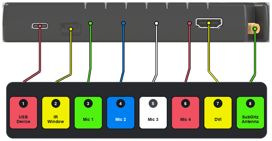
| # | Connector | What it's for |
|---|---|---|
| 1 | USB Device | The connection to a host PC. The console, the OneWili API and the FREE-WILi GUI app all reach the device through this port — see Connecting. |
| 2 | IR Window | A cut-out in front of the infrared transmitter and receiver, for line-of-sight control and capture. |
| 3–6 | Mic 1–4 | The four openings for the microphone array. |
| 7 | DVI | Video out to an external monitor or projector, driven by the display processor's HSTX peripheral. |
| 8 | SubGHz Antenna | The external antenna, shared by the CC1101 and the LoRa module. This is the same connector shown on the left edge below. |
Bottom edge
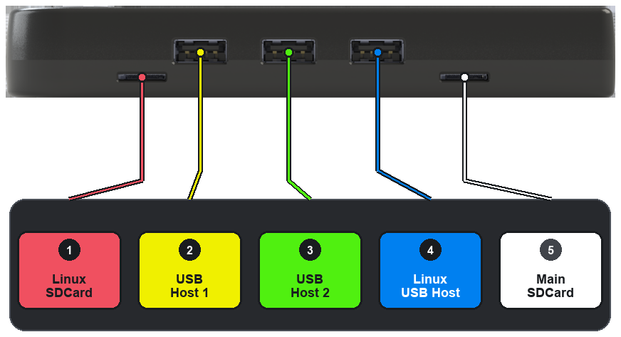
| # | Connector | What it's for |
|---|---|---|
| 1 | Linux SDCard | The microSD card holding the Raspberry Pi CM0's Linux install. |
| 2 | USB Host 1 | A USB host port — mouse, keyboard, joystick, GPS receiver, serial adapter, thumb drive. |
| 3 | USB Host 2 | A second USB host port, the same as the first. |
| 4 | Linux USB Host | A USB host port belonging to the Linux side rather than the display processor. |
| 5 | Main SDCard | The device's own file system. This card can also be handed to an internal USB card reader so a connected computer sees it as an ordinary mass-storage drive — see Transferring files. |
Each host port's 5 V is software-switched, so the device can power-cycle whatever is plugged into it.
Left edge
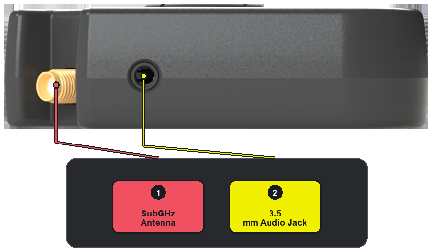
| # | Connector | What it's for |
|---|---|---|
| 1 | SubGHz Antenna | The threaded external antenna connector for the sub-GHz radio. NFC and 125 kHz RFID use internal antennas instead and have no external connector. |
| 2 | 3.5 mm Audio Jack | Headphone and speaker output, and microphone input, over one combined connector — so a standard headset works without an adapter. |
Right edge
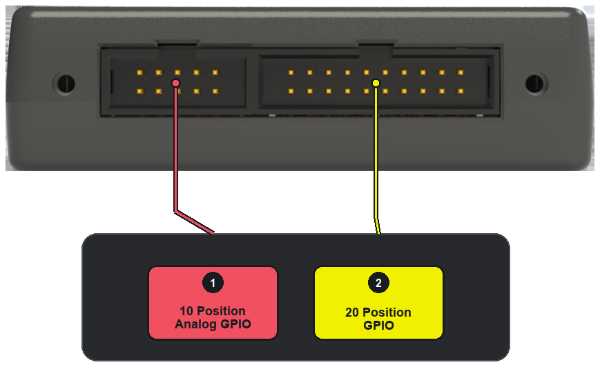
| # | Connector | What it's for |
|---|---|---|
| 1 | 10 Position Analog GPIO | The 10-pin analog header. |
| 2 | 20 Position GPIO | The 20-pin GPIO header — software-defined SPI, UART, I2C, CAN FD and general-purpose IO. |
Both headers are also what Orca expansion boards plug into. See Pinout for what sits on each pin.