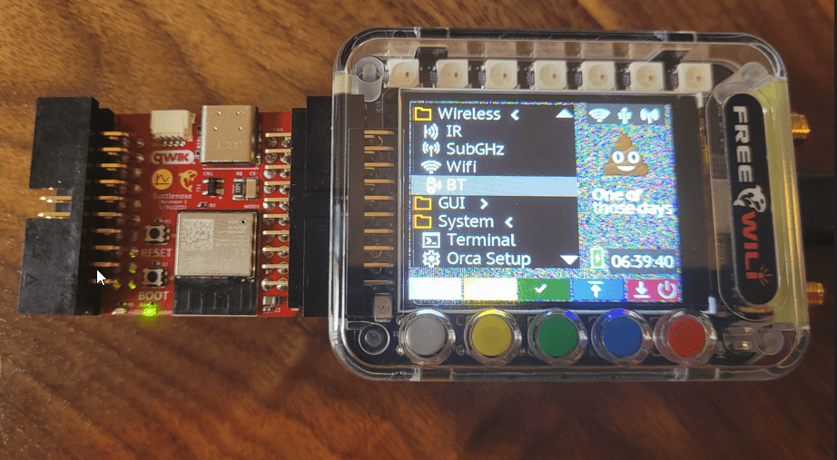
Bottlenose Hardware Hookup Guide
This guide covers the physical setup and connections for the Bottlenose WiFi Orca module.
Required Components
- 1 x Bottlenose WiFi Orca (ESP32-C6)
- 1 x FREE-WILi
Physical Connections
Connecting to FREE-WILi
Connecting the Bottlenose Orca to FREE-WILi is as simple as connecting the two 20-pin connectors together.

The Bottlenose Orca can only be powered through the 20-pin connector, meaning that FREE-WILi powers it via its 3.3V power rail.
The USB-C connector is only designed to access the ESP32's USB debug port for flashing custom user code and logging.
Communication between ESP32-C6 and FREE-WILi
The Bottlenose WiFi Orca communicates with FREE-WILi through the Orca connector interface using UART communication.
UART Pinout
| ESP32-C6 Pin | FREE-WILi Pin | Function |
|---|---|---|
| ESP_5V | 5V OUT | Power Supply (5V) |
| GPIO16 | UART1_TX_Out | Transmit Data (FREE-WILi → ESP32) |
| GPIO17 | UART1_RX_IN | Receive Data (ESP32 → FREE-WILi) |
| GPIO4 | UART1_CTS_IN | Clear to Send (Hardware Flow Control) |
| GPIO5 | UART1_RTS_OUT | Request to Send (Hardware Flow Control) |
| GND | GND | Ground Reference |
Both device's UART is configured with the following parameters:
- 3 Mbps Baudrate - Optimized for WiFi command and data transfer
- CTS and RTS Controls Enabled - Hardware flow control for reliable transmission
- 8 Data Bits - Standard data frame size
- 1 Stop Bit - Standard frame termination
- No Parity - Error detection handled at higher protocol levels
GPIO and Expansion
FREE-WILi still has several I/O pins available since Bottlenose only uses UART data pins with hardware flow control. These pins are exposed on the female 20-pin port on the Bottlenose PCB labeled as CN2. The pinout for this connector is the same as FREE-WILi's except for the UART TX and RX pins.
Bottlenose automatically sets the V PINS IN (Pin 4) to 3.3V, meaning all GPIO logic levels will operate at 3.3V. No manual voltage configuration is required.
CN2 Connector Pinout
The connector is arranged as a 2x10 header with the following pin assignments:
| Pin | Signal Name | Notes |
|---|---|---|
| 1 | SPI1-CS_OUT | Available for expansion |
| 2 | 5V OUT | From FREE-WILi |
| 3 | GPIO27_OUT | Available for expansion |
| 4 | V PINS IN | Auto-set to 3.3V by Bottlenose |
| 5 | UART1_Rx_IN | Used by Bottlenose |
| 6 | 3.3V Out | From FREE-WILi |
| 7 | UART1_CTS_IN | Used by Bottlenose |
| 8 | I2C 0 SCL | Available for expansion |
| 9 | UART1_TX_OUT | Used by Bottlenose |
| 10 | I2C 0 SDA | Available for expansion |
| 11 | UART1 RTS OUT | Used by Bottlenose |
| 12 | SPI1_RX_IN | Available for expansion |
| 13 | SPI1_TX_OUT | Available for expansion |
| 14 | GPIO26_IN | Available for expansion |
| 15 | SPI1_SCLK_OUT | Available for expansion |
| 16 | SWCLK IN | Available for expansion |
| 17 | GPIO25_OUT | Available for expansion |
| 18 | SWDIO | Available for expansion |
| 19 | GND | Common ground |
| 20 | GND | Common ground |
Signal Descriptions
Power Pins:
- Pin 2: 5V power output from FREE-WILi
- Pin 4: V PINS IN - Automatically set to 3.3V by Bottlenose
- Pin 6: 3.3V power output from FREE-WILi
- Pins 19-20: Ground reference
UART Pins (Used by Bottlenose):
- Pin 5: UART1 Rx IN - Receives data from FREE-WILi
- Pin 7: UART1 CTS IN - Hardware flow control
- Pin 9: UART1 TX OUT - Transmits data to FREE-WILi
- Pin 11: UART1 RTS OUT - Hardware flow control
Available Expansion Pins:
- Pins 8, 10: I2C SCL/SDA
- Pins 1, 12, 13, 15: SPI Chip Select, SPI MISO, MOSI, SCLK
- Pins 3, 14, 16, 17, 18: GPIO27, GPIO26, SWCLK, GPIO25, SWDIO
Qwiic Connector
The Bottlenose includes a Qwiic connector for easy plug-and-play connection to I2C sensors and modules from SparkFun's ecosystem. This connector provides access to the I2C0 bus (pins 8 and 10) with standard Qwiic pinout and 3.3V power supply.
The Qwiic connector allows you to easily chain multiple I2C devices without breadboarding or soldering, using SparkFun's extensive library of Qwiic-compatible sensors and breakout boards.